hnlzm@lvmeikapton.com
+86 13787123465


Hunan Lvzhimei New Material Technology Co., Ltd.

NameDescriptionContent
When Should You Replace Kapton Tape in High-Power LED Lighting? | https://www.lvmeikapton.com/
Source:
|
Author:Koko Chan
|
Published time: 2025-05-21
|
631 Views
|
🔊 Click to read aloud
❚❚
▶
|
Share:
This paper aims to determine the optimal replacement schedule for Kapton tape in LED modules by analyzing degradation factors such as UV exposure and thermal cycling. The study examines the life cycle of Kapton tape, degradation indicators, environmental stressors, and replacement protocols based on operating temperatures. Understanding these factors is crucial for maintaining LED system reliability and preventing premature failures.
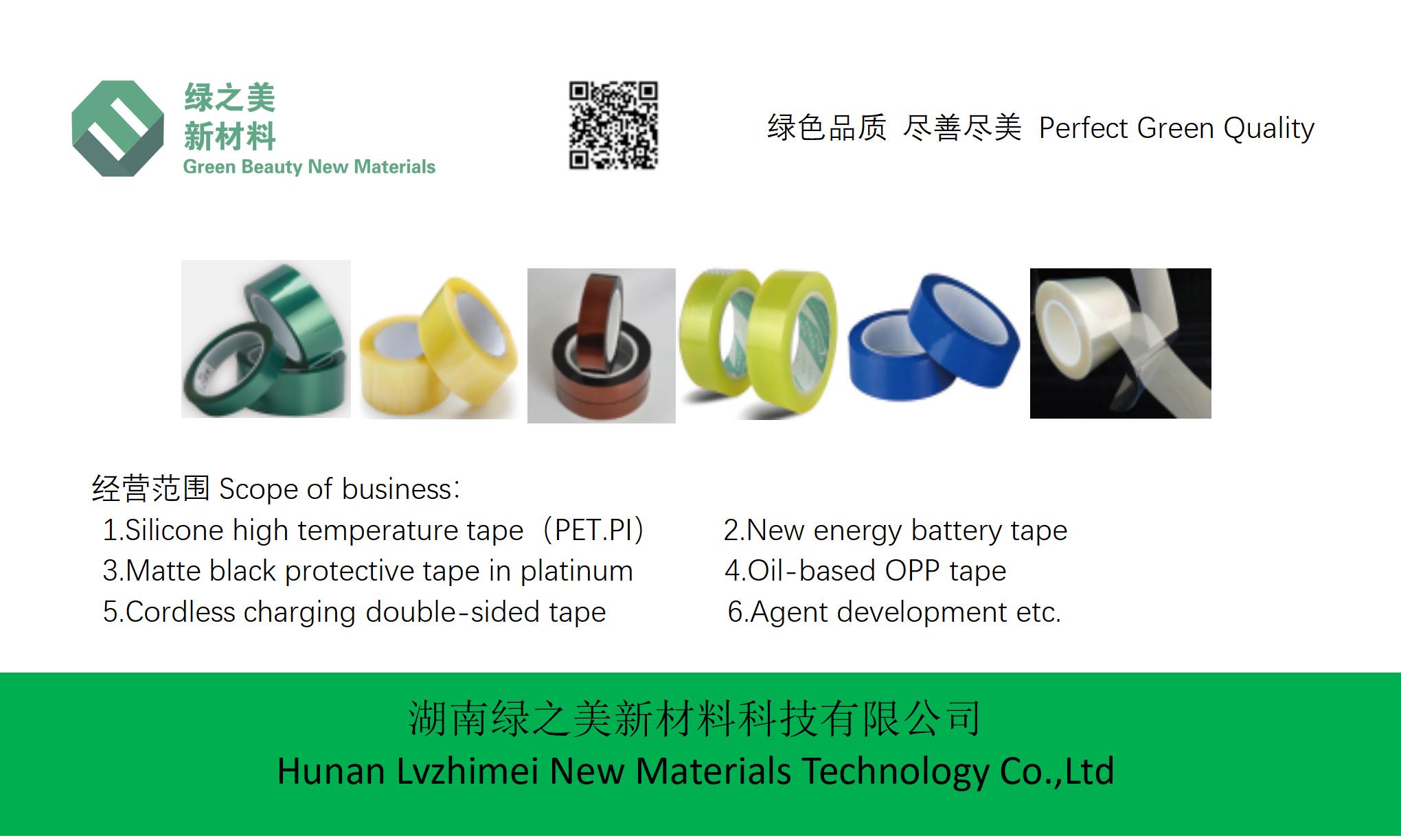
Keywords: Kapton tape, LED lighting, Brown circuit board high temperature tape, lvmeikapton insulating electrical tape.
Keywords: Kapton tape, LED lighting, Brown circuit board high temperature tape, lvmeikapton insulating electrical tape.
When Should You Replace Kapton Tape in High-Power LED Lighting?
AbstractThis paper aims to determine the optimal replacement schedule for Kapton tape in LED modules by analyzing degradation factors such as UV exposure and thermal cycling. The study examines the life cycle of Kapton tape, degradation indicators, environmental stressors, and replacement protocols based on operating temperatures. Understanding these factors is crucial for maintaining LED system reliability and preventing premature failures.
Keywords: Kapton tape, LED lighting, Brown circuit board high temperature tape, lvmeikapton insulating electrical tape.
1. IntroductionHigh-power LED lighting systems rely on Kapton tape (polyimide film) for thermal management, insulation, and mechanical protection. Kapton tape’s high-temperature resistance (up to 300°C), chemical stability, and excellent dielectric properties make it ideal for these applications. However, prolonged exposure to heat, UV radiation, and electrical stress can degrade its performance. Timely replacement is essential to prevent failures that may lead to system downtime, safety hazards, or costly repairs. This paper provides a comprehensive framework for assessing tape degradation and establishing replacement schedules.
2. Life Cycle of Kapton TapeKapton tape’s effectiveness evolves through distinct phases:
2.1 Installation and Initial PerformanceFreshly applied tape exhibits optimal adhesion, electrical insulation, and thermal conductivity. Its brown color (common in high-temperature grades) indicates the presence of reinforcing materials, enhancing durability. During this phase, tape functions seamlessly, protecting LED components from environmental stressors.
2.2 Degradation PhaseOver time, multiple factors initiate degradation, altering tape properties:
●
Chemical Breakdown: High temperatures accelerate polymer chain degradation, weakening the tape’s structural integrity.
●
Mechanical Stress: Repeated thermal cycling (heating and cooling) causes expansion and contraction, leading to microcracks.
●
Contamination: Dust, moisture, or corrosive gases can penetrate the tape, compromising insulation.
2.3 Failure PhaseOnce degradation surpasses critical thresholds, tape may delaminate, lose adhesion, or exhibit electrical breakdown. Failure risks increase exponentially, posing threats to LED module functionality.
3. Degradation IndicatorsIdentifying degradation early is vital. Key indicators include:
3.1 Yellowing and DiscolorationKapton tape’s color shift (from brown to yellow) signifies thermal aging. UV exposure accelerates this process, as polyimide absorbs radiation, causing photo-oxidation. Yellowing beyond 20% indicates significant polymer degradation (source: Lvmeikapton Technical Report 2023).
3.2 Adhesion LossReduced adhesive strength compromises tape’s bonding to substrates (e.g., circuit boards). Peel tests can measure adhesion retention; values below 10 N/cm suggest replacement necessity.
3.3 Electrical Property DeteriorationDielectric breakdown voltage (DBV) declines with aging. Periodic testing (e.g., ASTM D149) is recommended; DBV falling below 3 kV/mil mandates replacement.
3.4 Surface Cracking and DelaminationVisual inspection reveals microcracks or delamination. Advanced techniques like scanning electron microscopy (SEM) can detect early-stage damage.
4. Environmental StressorsEnvironmental factors dictate degradation rates:
4.1 UV ExposureUV radiation (280-400 nm) breaks polyimide bonds, causing embrittlement. Outdoor LED installations or unshielded indoor fixtures experience higher UV stress. Lvmeikapton’s PI material offers enhanced UV resistance, but protection degrades over time.
4.2 Thermal CyclingLED modules cycle between high operating temperatures (150-200°C) and ambient conditions. Each cycle induces thermal stress, accelerating tape aging. Systems operating at 200°C exhibit 2-3x faster degradation than those at 150°C (based on Arrhenius model studies).
4.3 Humidity and Chemical ExposureMoisture ingress can hydrolyze polyimide, while corrosive gases (e.g., H₂S) degrade adhesive layers. Enclosure design and environmental sealing mitigate these risks.
5. Replacement ProtocolOptimal replacement schedules balance cost, reliability, and safety:
5.1 Monitoring Methods
●
Visual Inspection: Quarterly checks for yellowing, cracks, and delamination.
●
Performance Testing: Annual DBV and adhesion tests.
●
Thermal Imaging: Periodic scans to identify hotspots indicating tape failure.
5.2 Temperature-Dependent Replacement Frequency
Operating Temperature | Recommended Replacement Interval |
150°C | Every 2-3 years |
200°C | Every 1-2 years |
5.3 Accelerated Replacement Scenarios
●
High UV exposure: Replace every 1.5 years (150°C) or 1 year (200°C).
●
Humid environments: Shorten intervals by 30-50%.
●
Critical applications (e.g., aerospace): Implement redundancy with dual tape layers.
5.4 Proactive Replacement Benefits
●
Preventive Maintenance: Avoids sudden failures and associated downtime.
●
Cost Efficiency: Replacing tape costs 10-20% of total module repair costs.
●
Safety: Minimizes risks of electrical shorts or thermal runaway.
6. Case Studies6.1 Industrial LED Lamp Failure AnalysisA 200°C-operating lamp failed due to tape delamination after 18 months. Post-mortem analysis revealed insufficient UV protection, highlighting the need for tailored replacement schedules.
6.2 Optimized Schedule for Street LightingBy implementing quarterly inspections and thermal imaging, a city reduced LED fixture failures by 40% over two years, saving $250,000 in maintenance costs.
7. ConclusionKapton tape replacement in high-power LED lighting requires a holistic approach. Monitoring degradation indicators, assessing environmental stressors, and adopting temperature-dependent schedules ensure system longevity. Proactive replacement not only enhances reliability but also mitigates safety and financial risks. Future research should explore novel polyimide formulations with improved UV and thermal resilience, further extending tape lifecycles.
Hunan Lvzhimei New Material Technology Co., Ltd.
Quick Links


Product Categories
© 2024 Hunan Lvzhimei New Material Technology Co., Ltd.All Rights Reserved. Designed by Erge
0731 - 89717319
hnlzm@lvmeikapton.com
+86 13787123465
Room 502, Chuangye Building, No186, Guyuan Road, High-Tech District, Changsha, Hunan, China
CONTACT


